![]()
![]()
![]()
![]()
![]()
Step 19: Adjust rheology and basal drag
In the parameter input (.in) file (example: iEarth5-049.in) we previously considered parameters such as density, thermal conductivity, thermal expansion coefficient, and radioactive heat production. These should not be changed lightly, because any change now would mean returning to Step 13 to recompute the layer thicknesses.
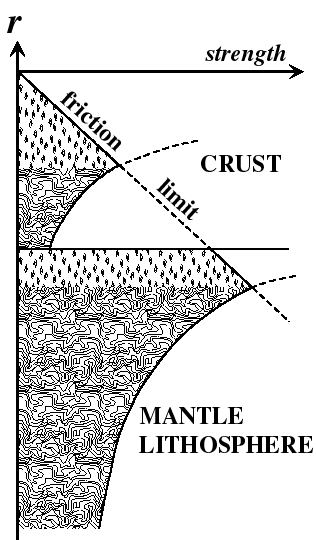
However, it is now time to consider the rheological parameters, which define the strength of the lithosphere for permanent (anelastic) strain. This rheology has three parts: friction, dislocation creep, and maximum yield stress. Schematically, a vertical profile of strength (defined as shear stress at a fixed strain-rate) looks like this:
In the parameter input (.in) file, friction is controlled by parameters in lines 2-5:
0.10 FAULT FRICTION COEFFICIENT 0.85 CONTINUUM FRICTION COEFFICIENT 1.00 BIOT COEFFICIENT (EFFICACY OF PORE PRESSURE) 0.00 BYERLY (0.-.99); FRACTIONAL STRENGTH REDUCTION OF MASTER FAULT |
All of the parameters above are dimensionless. Fault friction and continuum
friction will be applied to linear fault elements and triangular continuum
elements, respectively. The Biot coefficient is multiplied by the pore fluid
pressure (which I approximate as hydrostatic) before adjusting normal stress to
find effective normal stress; most people assume it is 1.00, but in a rock of
low porosity it could be less. The BYERLY
coefficient can be used to give an additional reduction of strength in
proportion to net fault slip (see Bird and Kong, 1994),
but only if data on net slip have been added to the fault element definitions
in the .feg file. Otherwise, this parameter has no effect.
The dislocation creep laws and the maximum yield stresses for crust and mantle are controlled by parameters in lines 6-10:
2.3E9,9.5E4 ACREEP (SHEAR STRESS COEFFICIENT OF CREEP LAW) 4000.,18314. BCREEP (ACTIVATION ENERGY/N/GAS-CONSTANT) (IN KELVIN) 0.,0.0171 CCREEP (DERIVITIVE OF BCREEP WITH RESPECT TO DEPTH; CRUST/MANTLE) 5.E8,5.E8 DCREEP (MAXIMUM SHEAR STRESS; CRUST/MANTLE) 0.333333 ECREEP (EXPONENT ON STRAIN-RATE IN CREEP-STRESS LAWS)=(1/N) |
These were defined in Table 1 and associated equations of Bird (1989). (Note that
most of these parameters can differ for the crust and the mantle, but that ECREEP must be the same in both layers.)
If you have access to a Windows computer, you can experiment with the effects of these parameters using Excel 97 spreadsheet In_Depth.xls, in which you choose a strain-rate tensor and then see graphically the effects of changing the creep and/or friction parameters.
The drag on the base of the lithosphere is governed by the mantle dislocation creep flow law (above) and some additional parameters in lines 11-15:
1412. 6.1E-4 INTERCEPT AND SLOPE OF UPPER MANTLE ADIABAT (K, K/M) 400.E3 ZBASTH: DEPTH OF BASE OF ASTHENOSPHERE AF PLATE WHICH DEFINES VELOCITY REFERENCE FRAME (AF, EU, NA, ...) 6 1.00 ICONVE:0=NONE;1=HAGER;2=BAUMGARDNER;3=PB2002;4=CONTINENTAL PB2002;5=forearc;6=inferred 2.E7 TRHMAX (LIMIT ON BASAL TRACTION) |
The first of these lines determines the asthenospheric geotherm
(approximated as an adiabat), which combines with the dislocation creep law for
the mantle to determine its strength. The depth to the base of the
asthenosphere ZBASTH
determines the thickness of the shear zone between surface plate motions and
lower mantle flow. (Here, I use "lower mantle" loosely to include the
transition zone, or everything which is not an olivine-rich rock.) Integer
index ICONVE determines
which pre-programmed pattern of lower mantle flow will occur at depths below ZBASTH, and the following parameter VTIMES is a dimensionless velocity scale
factor. Finally, parameter TRHMAX
is an upper limit on the basal traction. Please note that the way to get
"no basal drag" is to set TRHMAX
= 0.0; it is not enough to set ICONVE
= 0, because this just means that the lower mantle does not flow with respect
to Africa (but it continues to drag on the lithosphere).
A final rheological parameter to note is in line 16:
2.0E+12 TAUMAX (DOWN-DIP INTEGRAL OF SUBDUCTION ZONE TRACTION) |
This parameter TAUMAX is
an upper limit on the down-dip integral of the shear traction in subduction shear
zones. (Its value in N/m is about equal to the average shear traction in Pa
times the average arc/trench gap of about 2.0E5 meters.) This limit only
applies to fault elements with a dip of less than 19° , which are considered to be "subduction zones". For
justification of this low value, see Bird (1978; Geophys. J. Roy.
Astron. Soc.).
When you adjust these values, keep in mind that all are in Systeme Internationale (SI) metric units: lengths in meters (m), masses in kilograms (kg), time in seconds (s), stress in Pascals (Pa), and temperature in degrees Kelvin (K) measured from absolute zero.
Finally, notice that the first line of the file (below) is a descriptive title for the whole set of parameters. My custom is to save a parameter file under a new name (ending in .in) every time I make a change, and to record the name of the file in its own first line. This first line will be copied into all output from Shells, and from there it can be copied into maps, so that there will never be any question about which parameters were used in a particular calculation.
iEarth5-049.in: FFRIC 0.1, TAUMAX 2.0E12, ICONVE6#3, type-4A slabs; no internal VBCs |
![]()
![]()
![]()
![]()
![]()