Step 21: Tidy up the grid boundaries
Use command Edit / AdjustNode [within OrbWin] to click-and-drag node
locations to tidy up the boundary.
(Note: This is not technically necessary, but it results in prettier graphics.)
For large adjustments of the boundary, you may also want to delete or add
triangular elements.
You can delete elements with command Edit / Add/Delete Element, just by
right-clicking on the center-point (centroid) of any element you do not want.
Before you can add new elements, you may have to create their (outer) corner
nodes with Edit / Add/Drop Node and some left-clicks on the map.
Then, you can activate command Edit / Add/Delete Element, and define new
elements by clicking on their 3 corner nodes in counterclockwise order.
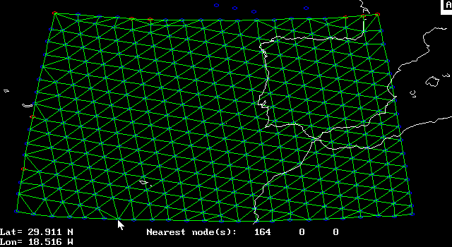
In the example below, deletion of some elements has left some free-floating
(unconnected) nodes along the North boundary. This must be fixed.
You can use Edit / Add/Drop Node and right-click to eliminate unwanted nodes
individually.
However, this would be a good time to try out the powerful command Tools /
Perimeter/Area Tests.
This command will ask you if you want to drop all unconnected nodes
automatically?
Also, you could try running command Tools / View Gaps/Overlaps as a further
(graphical) test of your gridís topology:
Just click on the centroid of any element and wait (about a minute) for the
display to finish updating; then do it again, as often as you like.
(Only the display is changing; your .feg file remains the same.)

Another note about the screen-shot image above:
Command View / Set Colors had been used to turn off the small
green triangles that (by default) mark the centers of all finite elements.
(Their purpose is to help you to distinguish between a triangular element
and a triangular hole in the grid.)
This makes a cleaner display, but if you need to see any problematic holes in
the grid area (if revealed by Tools / Perimeter/Area Tests, or by Tools / View
Gaps/Overlaps), then turn these triangle icons back on.