![]()
![]()
![]()
![]()
![]()
Step 35: Plot all aspects of preferred NeoKinema model with NeoKineMap
If you have not already done so, it is time to make as many different kinds
of maps of your preferred NeoKinema model as possible.
Many different kinds of map-views will give you material for:
ü Displaying in seminars, publications, and proposals;
ü Better understanding the kinematics of neotectonics in your study area; and
ü Possible clues about missing (or bad) data, that might be improved in the next study.
NeoKineMap can provide many
useful kinds of maps.
The list below does not include maps of your input datasets (faults
& their offset-rates, GPS, σ1h,
F-E grid, …),
which you have (presumably) already made before this step,
but only counts newly-available displays of the output from your
preferred model:
Ø Interseismic velocity field (Mosaic #11 and Overlay #19)
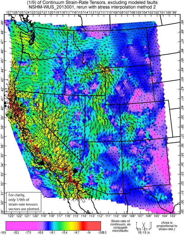
Ø Interseismic strain-rate field (Mosaic #12 and Overlay #20)
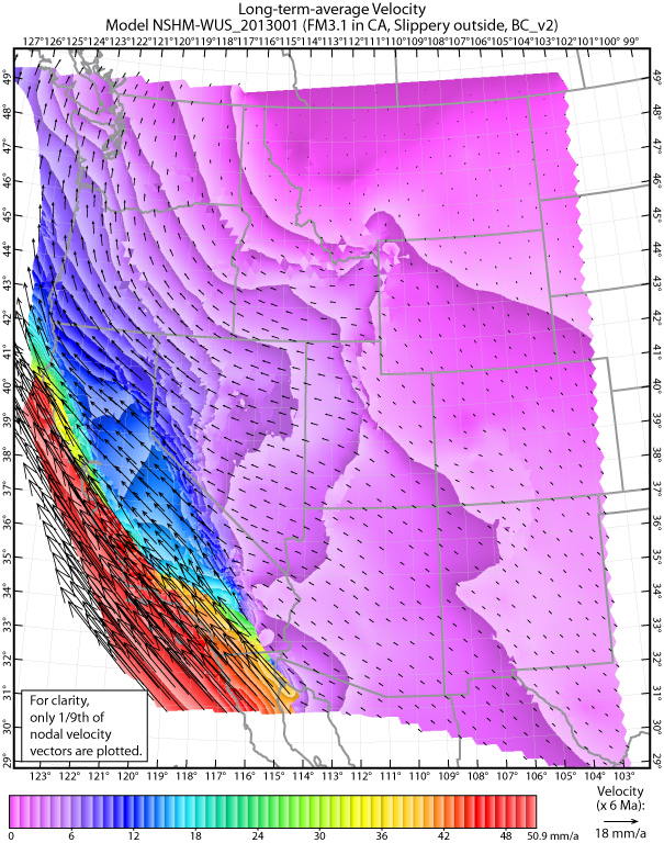
Ø Long-term-average velocity field (Mosaic #6 and Overlay #7)
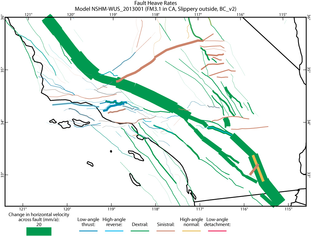
Ø Long-term-average fault heave-rates (Overlay #6; choice of 2 formats; see previous Step)
Ø Long-term-average strain-rate field, INCLUDING strain-rates due to faulting (Mosaic #7 and Overlay #9)
Ø Long-term-average strain-rate field EXCLUDING strain-rates due to faulting (Mosaic #9 and Overlay #10)
Ø Long-term-average rotation-rates about vertical axes (Mosaic #8)
Ø Principal axes and tectonic regimes of long-term-average strain-rate field (Overlay #11)
Ø Model-versus-actual GPS velocities, and unfit residuals, at benchmarks (Overlay #8; 5 options).
Some general suggestions about using NeoKineMap:
1.
The best number of Mosaic (full-color, “stained-glass”) layers in a NeoKineMap
plot is 0 or 1.
If you combine 2 (or more) Mosaics in one plot, only the last one (on top of
the stack) will be visible.
2.
NeoKineMap often follows the plotting of a Mosaic layer by
suggesting the type of Overlay
that would be most appropriate on top of it. Usually you should accept
these suggestions.
(If you want other Overlays as well, you can add them afterwards.)
3.
NeoKineMap has NO commands to control line-weights (i.e.,
widths in points) or line-colors
in Overlays. This is because it is so easy to change these in Adobe
Illustrator: Just use the
Selection Tool (black arrow) to click on any member of a group, and then edit
its line attributes.
Your change will apply, immediately, to the whole group.
In a similar way, you can change the size, or font, of any group of text labels
(or hide it).
After you review and adjust any map in Adobe Illustrator, it is a good
idea to also File /
“Save for Web and Devices” as a .jpg file. While you cannot edit
these .jpg files as easily
as the .ai originals, they can be made smaller and more portable, and
are good for placing into
a .ppt file (for a seminar) or a .docx or .pdf file (for a
manuscript or proposal).
If you publish map-figures in a journal that wants .eps files, note that
Adobe Illustrator
can also output your maps in that (rather inefficient) format, which can
be edited.
Below are some representative examples of NeoKineMap output maps.
The model is one of the two preferred models for the UCERF3 project, reported
in Field et al. [2013] and Petersen et al. [2014].
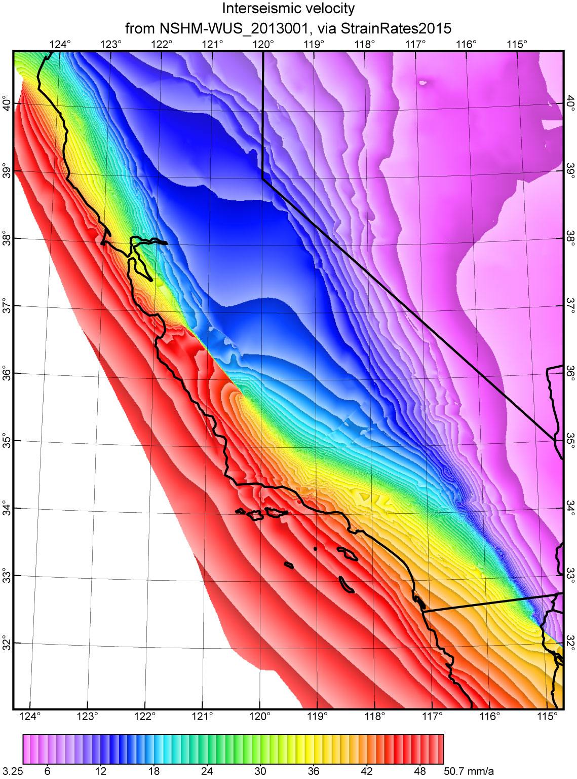
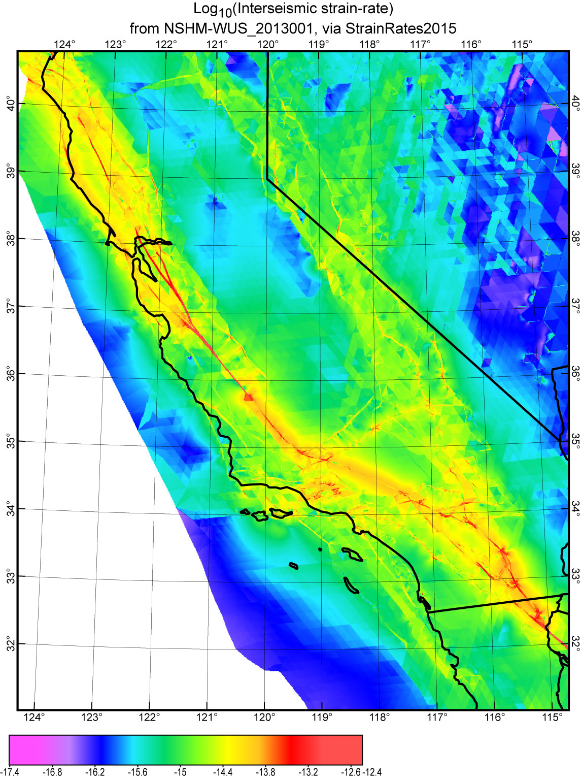
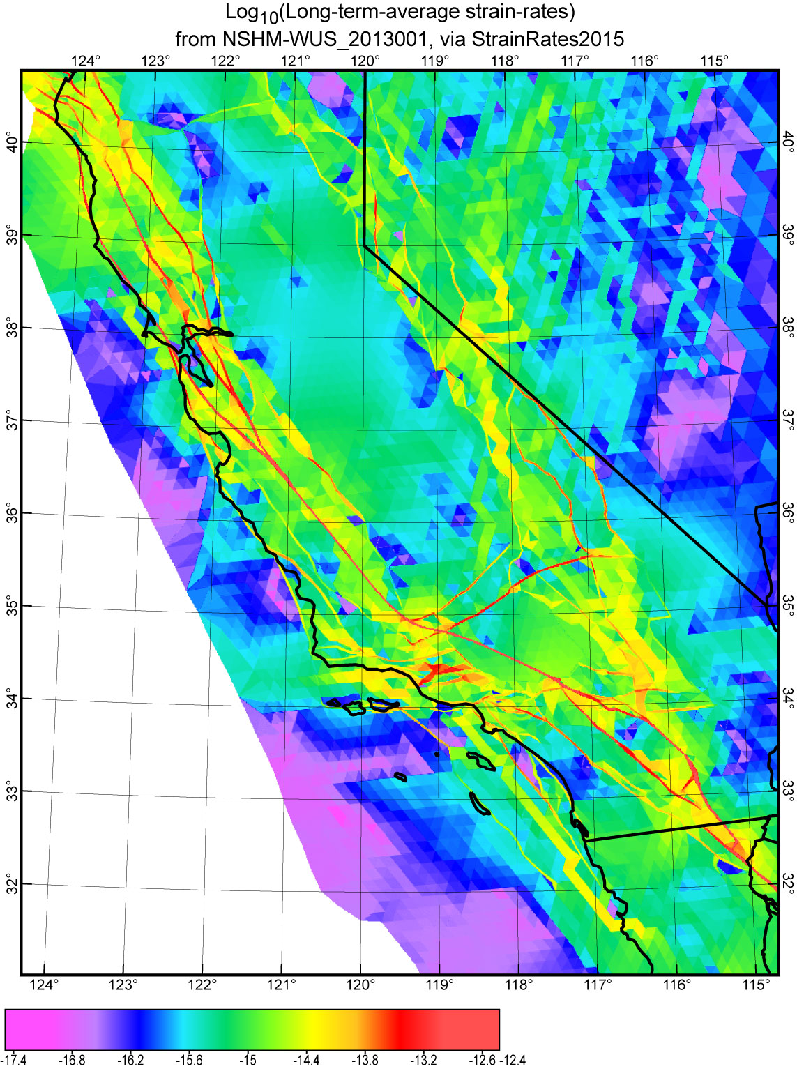
Note that some of these maps used post-processing utility StrainRates2015,
prior to NeoKineMap, for a more beautiful presentation.
This post-processor does not make any changes to the NeoKinema solution;
it merely computes that solution at many thousands of additional spatial
points, for better maps,
and also for easier comparison to deformation models by other investigators
using other software.
The latest update of this code is StrainRates2016.
One final TIP: At the start of this map-making
step, you probably made some adjustments to the map-projection
and/or virtual-paper size that define the “frame” for each map. Once you have
these adjusted to your liking,
it is a good idea to save your choices for future map-plotting.
To do this, go to the “home” folder in which NeoKineMap is started on
your computer, find the latest Map_Tools.ini
file,
make a copy, and save it with your project files (possibly in the folder where
you save your basemap .dig files).
![]()
![]()
![]()
![]()
![]()